Dynamic Jigsaw Piece in Blender
Goals
- To create a jigsaw piece which can then be randomised via code.
- The jigsaw piece is to be used as test data for a jigsaw solving application, so it needs to be able to be rendered in a vaguely realistic manner (as if someone took a photo of a jigsaw piece using their phone.)
- Apply a texture to the jigsaw piece that can be randomised via code.
Existing Puzzle Pieces (and Generators)
“Puzzlegen” - Provides functionality for turning an image into a full jigsaw puzzle using Blender. Not free, currently cost $10. Not suitable.
“GVC Puzzles Dataset” - Chopped up images. The images are not shaped like jigsaw pieces and are purely 2D. Not suitable for emulation a real image of a jigsaw piece.
“Jigsaw-Puzzle on Kaggle” - Not really a “jigsaw”, more visually similar to one of those slide puzzles. Not suitable for use.
“Jigsaw puzzle pieces data set” - Images of multiple jigsaw pieces. Along with other issues, it only contains a very small number of images/pieces. Not suitable.
Creating the Base Piece
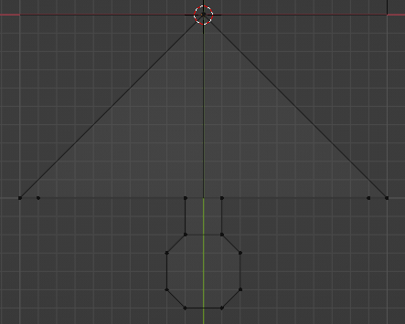
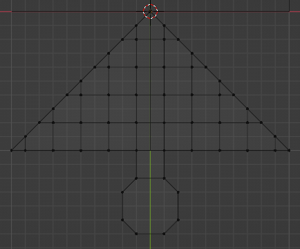
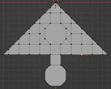
To start, I created a quarter of a jigsaw piece aligned to a grid for simplicity. I used n-gons (faces connected to more than 4 vertices) to simplify the shape. The piece is completely flat and has no height (this can be achieved with modifiers later on).
I used an “Array” modifier to duplicate the base mesh around a rotational point. Rotating the point 90 degrees gives each piece a +90 degree rotation compared to the previous. Creating three other meshes will be enough for a full piece. This makes creation of the mesh much simpler and allow for easy randomisation later on (can randomise each quarter individually, then combine.)
Use of Modifiers
To turn the base mesh into a full jigsaw piece, I used a number of modifiers:
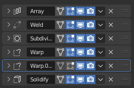
Explanation of modifiers:
Array - Duplicates the quarter piece 3 times.
Weld - Removes duplicated vertices caused by the array modifier by merging them into one.
Subdivision Surface - Increases the resolution of the mesh by splitting the faces into smaller faces. Has the effect of making the mesh smoother and more rounded, which is why the base mesh can be so angular without causing issues in the final piece.
Warps - Handles the distortion of the mesh so the piece can form a realistic jigsaw piece shape.
Solidify - Extrudes the mesh vertically, giving the jigsaw piece thickness.
These modifiers create the following out of the base mesh:
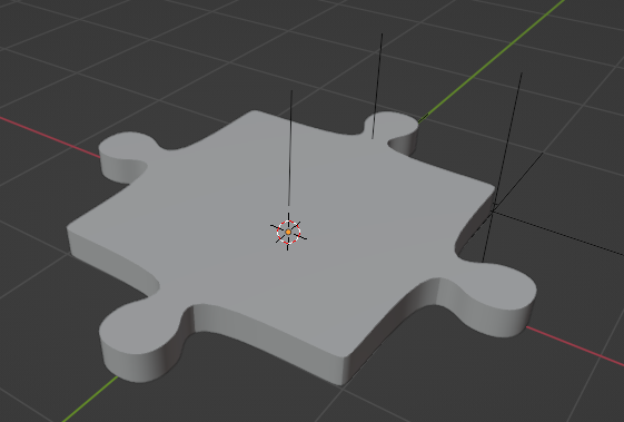
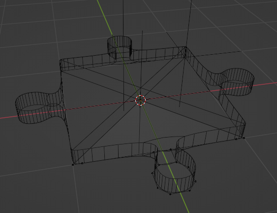
And in wireframe (notice how the vertices are only displayed on the closest quarter in the original mesh shape as all the others are created via modifiers):
Applying Randomness to the Piece
Randomness is applied to the piece with the use of the warp modifier. This modifier allows vertices to be displaced based on two defined locations; the origin location, and the target location. In the following examples of the warp modifier, the origin and target locations are represented by the “plus” shapes. I am moving the target location, which warps the vertices around the origin location to the target by an amount determined by the vertex’s distance to the origin.
The warp modifier can handle full XYZ movement (although I am only using XY for this project), as well as rotation for a fully randomised piece.
Notice how the mesh distorts when it is warped too far from the original location or when it is scaled too high. This is because the base mesh has too few vertices for the modifier to properly distort.
Fixing Mesh Distortion
To fix the mesh distortion, I edited the base mesh to include many more vertices within the large n-gon surface. I also adjusted the order of the modifiers so that subdivision surface is after the solidify, so the mesh has more vertices along its height.
I also modified the position of the connector warp modifier origin as I found that it give it a more realistic shape.
Dynamic Connectors
Next, I added dynamic connectors to the base mesh to increase the randomness. I achieved this by adding more vertices and edges inside the mesh to cut out the inner connector:
I then used vertex groups to define the vertices that should be shown for each of the three edge types. Each side can be either an “in” connector, an “out” connector, or an “edge” side. This allows corners to be created via two edge sides that are next to each other. Vertex groups can be shown and hidden via the “Mask” modifier as seen below:
This approach could technically allow invalid jigsaw pieces to be created, e.g. pieces with all “edge” sides. However, they will be the minority and should not have a noticeable impact on the quality of the dataset.
Applying the Texture
UV Unwrapping Issues
I used Blender’s default UV unwrapping and applied a material with an image. Because I am still working with the base mesh rather than the full piece, it can only unwrap a quarter of the mesh. The issue with this is that when the array modifier duplicates the mesh, the UVs of all the pieces are the same as the base, leading to pieces with the same texture rotated around the centre.
Fixed with Nodes
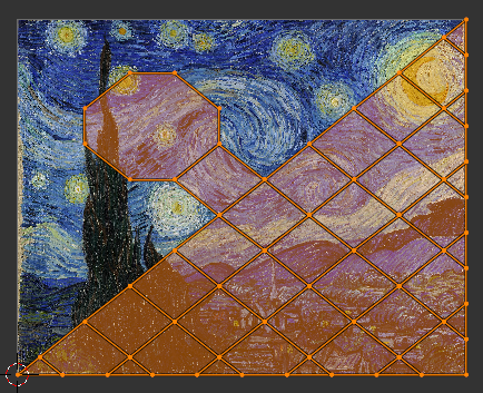
This UV issue can be fixed by setting up the material nodes of the base mesh to use object texture coordinates rather than UV. This means that the each vertex’s texture coordinate is based on its position relative to the origin of the object. Importantly, this is applied after modifiers, so there is no longer an issue with the duplicated meshes.
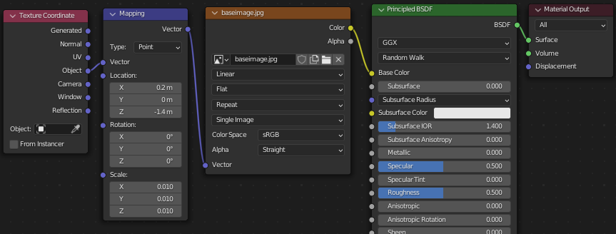
I used a “mapping” node to control the scale and position of the texture on the piece. This means that I can generate different sized jigsaw pieces without actually changing the size of the piece and changing the size of the texture instead.